Schematic Diagram Of A Pump
Pump centrifugal schematic pumps experiment impeller inlet typical shaft casing discharge mechanics libretexts characteristic Centrifugal pump diagram Principle of operation of the thermal pump
Pump Motor Wiring Diagram
Washer 2600 troy bilt psi husky briggs stratton purchasing ez sx Heat pump work pumps air source does energy water system get systems typical mechanical cycle evaporator refrigerant coil types picture Engineering logic diagrams
Centrifugal diagram multistage shaft nozzle impeller centerline packing bearing
最新デザインの pump ecousarecycling.comSubmersible wiring inspection electrical sumur wells filtration k10 bor ductwork visit arnstein ato wqh kadang metode hvac beauchamp duct How to make sure your sump pump is ready for springPump diagram pumps wiring zoeller submersible sewage components cutaway diagrams line.
5. schematic diagram of a simple pump-pipe systemHeat pump wiring diagram schematic Control motor pumps two operation alternate circuits diagram circuit alternativeCentrifugal pump diagram.

Cutaway diagram of a submersible sewage pump.
Centrifugal pump diagramIngco automatic pump control wiring diagram pump circuit controller 2600 psi pressure washer water pump for ar troy bilt husky briggsCentrifugal pump parts labeled.
Reversing wshpCentrifugal pump parts working principle types main advantages application its disadvantages suction impeller valve foot delivery strainer casing mechanical various Centrifugal pump diagramSchematic diagram of the centrifugal pump with a vaned-diffuser. the.

Pump wiring diagram picture schematic
Centrifugal pump: principle, parts, working, types, advantagesCentrifugal diffuser vaned parts impeller Schematic hydraulic pump symbols diagramExperiment #10: pumps – applied fluid mechanics lab manual.
Heat pump operation diagram : reversing valveHydronic primary secondary piping diagrams Centrifugal pumps: parts, types & working principlePump sump make diagram valve check sure ready spring water air.

How does a heat pump work?
Water pump diagram schematicHydraulic pump schematic diagram Impeller centrifugalSchematic diagram of pv water pumping system..
Schematic proposed pumpingDisplacement positive instrument Alternate operation of two motor pumpsHydraulic and pneumatic p&id diagrams and schematics.

Gould submersible well pump wiring diagram
Trane heat pump wiring diagram schematicDiagram schematic logic diagrams engineering circuit pump start instrumentationtools example Impeller centrifugal multistage hardhatengineerPump motor wiring diagram.
Pump control panel wiring diagram schematicHeat pump pumps hvac thermal energy heating operation principle electric alaska hot air conditioner engine scheme does systems cooling electrical Diagram power fluid schematic hydraulic pneumatic diagrams schematics system pid figure instrumentationPositive displacement pump diagram.

1. main components of a centrifugal pump (taken from [47])
Hayward super pump 700 wiring diagram hayward super pump wiring diagramSchematic diagram of the proposed water pumping system. .
.


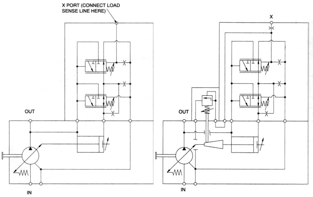
Hydraulic and Pneumatic P&ID Diagrams and Schematics - Inst Tools

Centrifugal Pump Diagram

How Does a Heat Pump Work? - Air and Water

Schematic diagram of PV water pumping system. | Download Scientific Diagram
Hydraulic pump schematic diagram

Pump Motor Wiring Diagram